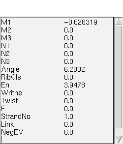
An example of the Numeric Data module.
The following sections describe the usage of modules which may be utilized to visualize specific solutions contained within a bifurcation diagram. These modules communicate with VBM through an interface described in Section.
An example of the Numeric Data module.
This Data Probe is quite simple but has been found to be very useful. On the left it lists all of the names that have been defined in the VBM file and on the right it shows the values of all of the columns at the marked point. The bar at the top of the window is the same color as the marker sphere to which the Data Probe is attached.
This is a general module used to visualize AUTO generated solutions, either by reading them from an AUTO file (of fort.8 type), either by reconstructing them with an IVP solver, or by combining the two methods.
To function, this module needs two tags specifying the way it should use the list of variable names and the initial data coming from the bifurcation diagram. They concern the definition of the types of columns in the VBM files, which can be equation variables or parameters.
Reconstruct_EQ
Reconstruct_PAR
For example, if the VBM file contains the following tags:
# Reconstruct_EQ 0 14
# Reconstruct_PAR 15 34
then the 15 first columns of the VBM files are the initial values of the equation variables (i.e. for s=0.0), while columns from the 16th to the 35th are the parameters in these equations. This means that the 15 first names in the list will be used to display the solution, while the 20 next names can eventually be used during the reconstruction.
If these tags are absent, then the module can use the following tags instead:
AUTO_EQ
AUTO_PAR
For any of the two tags, if the identity of the first column is negative, then the module will add to the initial data a number of 0.0 values equal to absolute value of this negative number. This feature has been added for compatibility with ancient VBM files, and can be useful when the initial data saved in the VBM file for each point is smaller than the number of equations in the right hand side file. For example, if the VBM file contains the following line:
# Reconstruct_EQ -2 14
then the module will use the 0 to 14 names in the file. Then at reconstruction time, the initial data file will contain the 0 to 15 real values attached to the current point, plus 2 more 0.0 values. This tag means that the solution needs 17 equations for reconstruction, but the VBM file has only saved 15 initial values. Note that in this case, the 16th and 17th columns will not be available for visualization. We do not recommend the use of this feature when constructing new VBM files.
If the solution is reconstructed both by using a fort8 file and then by calling an IVP solver, then the module needs both Reconstruct and AUTO tags. The AUTO tags will design the columns in the fort8 file, while the Reconstruct tags denote the columns built by the IVP solver.
These tags are used to set the names of the columns in the solution, but also to generate the initial data and the parameter values for reconstruction with the IVP solver, so they should be present in any case.
At last, this module also uses a special tag
Reconstruct_names name1;name2;...
If this tag is present, then the module will use this list of names for reconstruction, instead of the general names from the VBM file. If the list of names is longer than the specified number of equations for reconstruction, then the module will add extra values of 0.0 to the initial data to make the two lengths equal. If the number of columns generated by the IVP solver is bigger than the list of names, the resulting data will be respectively truncated. In the end, the visualized solution will have a number of columns exactly equal to the length of the given list of names for reconstruction.
For example, if the VBM file contains the following tags:
# Reconstruct_EQ 0 5
# Reconstruct_names x;y;z;q1;q2;q3;q4
then the module will add one extra 0.0 value to the initial data, and keep all 7 columns of the result for visualization.
On the contrary, if the VBM file contains the following tags:
# Reconstruct_EQ 0 8
# Reconstruct_names x;y;z;q1;q2;q3;q4
then the module will write 9 initial values to be used by the IVP solver, but only keep 7 columns of the result for visualization.
This module also uses an environment variables to define how it should
compile the IVP solver. VBM_VIEW_AUTO_IVP_FORTRAN_COMPILER
must be set to a command line which can be used to compile the Fortran
IVP solver. It allows the you to give any additional flags needed for
your problem and compiler. The default value is f77 -O. If
this is inappropriate for your system this module will fail. Note that
when the module is loaded, it will try to compile the problem, and
will normally succeed ifthe apropriate tags and the Reconstruct data
block have been given (see the
subsection).
For the AUTO generated fort.8 files, this module also uses the
AUTOFort8_file
tag. If VBM detects the presence of this tag in the description of the current point while loading the module, it will select the "AUTO fort8 file" option in the Data Options page. The use of this tag is the same as for the AUTO fort8 dataprobe.
This tag tells the module where it can find the full solutions, as produced by AUTO, so that it can produce graphical representations of the solution. An example of the usage of this tag follows.
# AUTOFort8_file /home/lcvm1/redrod/bvp.fort8 1
0.0 0.0 -1.5364222362e-31 0.0 0.0 0.0 1.0 0.0 0.0
In the previous example the AUTOFort8_file tag is followed by
the full path to the desired AUTO data file. Such files are known as
fort.8 files and we refer to the AUTO documentation for
further information on the structure of such files. The final entry
in the tag is an integer which gives the label of the solution within
the AUTO data file to visualize (AUTO fort.8 may contain more
then one solution).
Independently of the data option, this module uses the
VBM_extra_data_file
tag to provide the name of the file containing the definition of extra columns in the solution.
For example, if the VBM file contains
# VBM_extra_data_file ./fq.sav
then the extra column defined in the file named as the argument of this tag will be automatically loaded as the VBM file is read.
All the options of this module use the variable names defined in the
VBM file. If these variables are not defined, and the fort8 option is
chosen, then the variables get assigned the names x0,x1,....
Finally, this module uses a compute engine block specially designed for it. Its name is "Reconstruct" and the information it should provide to the module is the names of the working directory and of the problem file. See the IVP Options subsection for more details.
This module is based on DataViewer, and uses the following keyboard and mouse binding to manipulate the visualization. Note, this information is repeated in several sections since it is the same for all DataViewer based modules. We include it to make each section as self-contained as possible.
Keyboard bindings
Perform rotations about the vertical axis.
Perform rotations about the horizontal axis.
Perform rotations about the axis "coming out of the screen".
Translate the object horizontally.
Translate the object vertically.
Zoom the object.
Mouse bindings
Performs rotations of the solution based upon the virtual trackball paradigm.
The solution continues to rotate in the same direction as it was rotating when the button was release.
The solution stops rotating.
Translates the solution based upon the movements of the mouse.
As the mouse is moved up the solution is moved closer to the eye-point, and as the mouse is moved down the solution is moved further away from the eye-point.
Note that this module uses two control panels. The first one, called "Data control", is used for all the choices and actions concerning the numerical data in the module. The second one, called "View Line Control", is used for all the choices and actions concerning the graphical part of this dataprobe.
In principle, these control panels are not to be simultaneously active on the screen. By pressing the button called "Deiconify panel" from the main window of the module, one can activate the graphical panel. The opposite button on this window, labeled "Iconify panel", will iconify any of the two panels that is active.
While working with each of the two panels, the other panel can be deiconified by pressing the "Switch Panel" button on the button of the panel. This action will iconify the active panel before activating the other one. They could be both activated by directly clicking on their icon on the screen, but this procedure is not recommended.
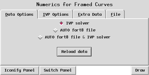
The data control panel is shown in Figure. Note, some of the control panels are common to several modules. We have chosen to describe them multiple times to make the documentation for each module self contained.
The numerical control panel for the
General AUTO Data Probe module.
This page allows the user to choose between the three options available in this module for generating the solution, which are the IVP solver,the AUTO generated fort.8 files and a combination of both of them. In the first case, the solution is reconstructed with the IVP solver starting from its first point (for s=0.0) stored in the VBM file. In the second case, the solution is read from the fort.8 file. In the third case, the solution is read from the fort8 file, and then new columns are added to it by calling an IVP solver.
The advantage of the IVP solver is that the data storage is much smaller, since the original fort.8 file may be discarded. The disadvantage is that if the ODE is stiff then the solution reconstruction may not be possible. The user must decide which mode of operation is more appropriate for their problem.
The 2 first data options use the Reconstruct tags, and if these tags are not specified, the AUTO tags (see beginning of the section for more details). The last data option uses both categories of tags the following way: the AUTO tags denote the columns in the fort8 file, while the Reconstruct tags the columns added afterwards by solving an IVP problem.
The two options using AUTO fort8 files are implemented with help of a
specialized file indexer that transforms fort8 files from sequential
file into direct access files.. The VBM file should contain for each
point a tag with the name AUTOFort8_file and two fields, the
first one specifying the name of the fort8 file, and the second
providing a label that identifies the point inside the fort8
file. This label corresponds in the fort8 file to the fourth value on
the first line of the data linked to the point. For example, if the
VBM file contains the line:
# AUTOFort8_file ./bvp.fort831 5
then the data following this tag corresponds to the point of label "5" in the fort8 file with the name "bvp.fort831". In that file, the data corresponding to this point starts with the line:
1 30 4 5 1 1 41 16 251 10 4 20
where the fourth number represents the label.
The AUTO fort8 file indexer will create an index file with the same name as the fort8 file and with the ".ind" extension. If this file is not present, the dataprobe will create it, which can take some time. In this case, a message of the type
indexing file: bvp.fort831
will be displayed on the standard output. When the indexation is completed, the file indexer displays a second message of the form:
...done
Whenever necessary, the dataprobe will complete the index. For example, more points could be added to the fort8 file by continuation. When you try to visualize such a point, the file indexer detects that the point has not yet been indexed, and rereads the fort8 file to complete the index. In this case, a message of the type:
completing index for file: bvp.fort831
followed by the same ...done message in the end.
The fort8 file indexer can fail to find the point with the given label from the VBM file. In this case, it will give you an error message containing the label that does not exist in the fort8 file. This situation can occur if the fort8 file has been rewritten, and either the VBM file or the index file contains information from the previous version of the fort8 file. In case of doubt, you can erase the index file, so that the next time you run VBM the index is rebuilt. If this doesn't work, then you must rebuild the VBM file from the fort8 file.
The last button on this page, labeled "Reload data", should be pressed in the following situations:
Pressing this button will have the effect of regenerating the solution considering all the options and actions associated to it. You also need to press the "Draw" button before seeing any change.
This page is shown in Figure and concerns the data options using an IVP solver. It allows the user to manage the executable linking their problem to the IVP solver and to choose the precision of the solution reconstruction. The compiler is automatically called when the module is loaded, unless the VBM file contains tags indicating the preference of a fort8 file instead of an IVP solver.
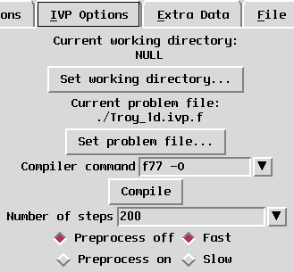
The IVP solver page for the
General AUTO Data Probe module.
The IVP solution reconstruction functions by compiling an AUTO "right hand side" file, written in Fortran, with an IVP solver (also written is Fortran). This page is used to control the compilation of the Fortran program.
The top group of widgets displays the name of the current working
directory and allows the user to set it. The "Set working directory"
button calls a file dialog inside which this directory can be
selected, and then modifies the preceding text according to the
choice. This directory is used by the executable of the user problem
to write temporary files. If this directory is set to "NULL" (which
is the default), then the module will create a temporary directory
itself (normally in /usr/tmp).
The second group of widgets displays the name of the problem file, and
allows the user to set it. If the problem name is an executable (ended
by a ".exe"), then it is copied into the working directory under the
name "problem.exe", unless it is identified as the "problem.exe" in
this directory. This module uses the same AUTO Fortran file as
described in
Section, and the main point
to remember is that the STPNT function must be commented out.
The two previously described parameters (the working directory and the problem file) are NULL by default. Their value can also be automatically set for each VBM file by including a special compute engine block in it. The compute engine block must have the following structure:
##Begin VBM_Compute_Module
NULL
NULL
./work/problem.exe
./work
Reconstruct
Example of reconstruction block
##End
The first two lines, containing "NULL", are not used by this module, but must be present for reasons of block formatting. The next line contains the name of the user problem file for reconstruction. As mentioned before, if this name ends by ".exe", it will be copied into the working directory. If the path to the problem is not absolute, be sure to run VBM from the right directory.
The fourth line contains the name of the working directory. The next line contains the name of the block. The last line contains a comment that is not used by this module.
If this compute engine block is not present in the VBM file, then this module will search for compute engines with the name "VBM_1D_AUTO". If several such compute engines exist, then the module will use the last one it encounters.
Note: even if the VBM_1D_AUTO compute engine specifies a working directory, this module will not use it, in order to avoid conflicts with any running compute engine. Thus, the name of the problem file is the only information the module takes from the compute engine. We recommend to check the default information in this case before the Fortran program is compiled.
The next typein shows the compiler command line, which should contain the name of the fortran compiler and all the options needed for the problem. The default value for it is "f77 -O". If this is not appropriate for your system you may override this default by setting the
VBM_VIEW_AUTO_IVP_FORTRAN_COMPILER
If the "Compile" button is pressed the Fortran program will be compiled and the communication will be initiated.
The precision of this solver can be set within the "Number of steps" typein. The default step of the solver is 0.005 corresponding to 200 generated points. Note that the solution will contain 201 points, corresponding to the initial point plus the generated ones.
The Preprocess on/off buttons allow the use of a preprocess option for the reconstruction. For this, in the file "problem.f" you must define a function
SUBROUTINE PREPROCESS(NDIM,U,PAR)
that will be called at each step before any solution reconstruction. In this function, the initial data coming from the VBM file can be preprocessed if it doesn't match the user's needs. For example, in the "perfect_with_energy_demo" using the
dna_problems/perfect_old/dna.f
the VBM file only contains the initial values for m1, m2, m3, n1, n2, and n3, but the reconstruction needs all the 15 equations defining the elastic rod. The module is able to complete the initial data from 6 to 15 using the "Reconstruct_names" tag, but this is not enough to reconstruct the problem correctly. The preprocess function is designed to fill this sort of gap. Its main goal is to assure backward compatibility with old VBM files, but can have larger usage too.
Finally, the Fast option chooses an IVP solver that constructs the solution in each point based on the previous point. On the contrary, the Slow option forces the solver to restart at t=0.0 in each point. This option is still necessary when the first one fails, which could be the case on SGI machines.
This page is shown in Figure and contains all the operations needed to add new columns to the solution.
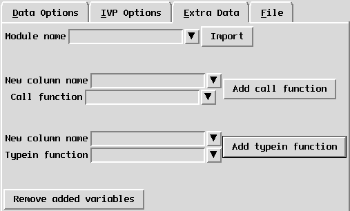
The Extra Data page for the
General AUTO Data Probe module.
Importing modules
The first operation that can be performed is importing a module. As the new columns are computed, they could need to call a function defined in a Python module outside VBM.
To import a module, you must type its name in the typein at the top of the page, labeled "Module name". Then you must press the "Import" button. Then any function defined inside it can be called by its name.
For Python programmers, the described actions have the following effect:
from 'module_name' import *
Call functions
The next operation that can be performed on this page is adding a new column by calling a function. For this, you must do the following:
s, f, q, r
and you use "q" as parameter in the function call, then this parameter
will have the integer value 2. You can also pass the whole data matrix
to the function, by using the name "solution".
Note: If you define your function in a module, then you must import
the module for the computation of the new column to work. Typein functions
The last action on this page is adding a new column as a typein expression. The main difference between this operation and the previous one is that for the call functions, the new column is computed in one function call. In the present case, the new column is computed point by point, and any function used inside its expression is called for each point of the solution. Thus, this type of computation can take longer. it is recommended to use it only for simple expressions.
To add a new column by a typein expression, you must do the following:
Removing the extra data
The last button on this page, labeled "Remove added variables", clears
all the added variables. It will delete all the columns added to the
data any action taken on this page. It will also delete the columns
produced by the extra variable file if the VBM file contains the
VBM_extra_data_file tag (see
subsection). All the menus based on the variable names will also
be updated, and the data reloaded, so be sure you are not currently
using any of the extra column for visualization when you press this
button, otherwise the result may be hazardous. You do not need to
press the Draw button after this action.
This page groups all the operations linked to saving and reading the extra columns added in the previous page to and from a file.
The first button, labeled "Save added variables" activates a save file dialog. If a file name is entered in this dialog, then a file with this name will be created, and all the extra columns will be saved in it. This file will contain:
When the file has been created, the filename can be used in the VBM file as an argument for the
VBM_extra_data_file
If more columns are added after an extra data file has been saved, they can be saved in the same file as before. By this action, both the previous columns and the new ones will be in the same file. If the name of this file has been added to the VBM file as a tag, then all the extra columns will also be loaded at start.
The second button in this page, named "Read variables file", activates a read file dialog which can be used to read in a file created by pressing the first button on this page. If the file has been created in another manner, hazardous effects may result.
A file created in one VBM file can be read inside another VBM file, as long as the variable names used by the new columns are consistent. Though, this operation can be dangerous, so we do not recommend it.
This page contains two buttons, used respectively to iconify and deiconify the visual panel.
The visual control panel is shown in Figure. Note, some of the control panels are common to several modules. We have chosen to describe them multiple times to make the documentation for each module self contained.
The visual control panel for the
General AUTO Data Probe module.
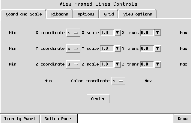
This page allows the user to select what columns of the data to plot in the Data Probe viewer. The X coordinate,Y coordinate, and Z coordinate rows allow manipulation of the spatial coordinates which are plotted, while the Color coordinate row controls the use of a column of data as a color (more detail on the coloring feature can be found in Section).

An example row of the "Coord and Scale"
option page.
Each row begins with a label which shows the minimum value for the selected column and ends with a label which shows the maximum value (as denoted by "a" and "e" in Figure). These minimums and maximums are taken over the entire solution. The selection widget (denoted by "b" in Figure) allows the user to select which column of the data they wish to visualize. The first type-in widget (denoted by "c" in Figure) allows the user to select a scaling value for the column. Each value in the column is multiplied by the scaling value before being plotted. A useful trick is to scale some value by 0 to get a "plan view" of the other two columns. The second type-in widget (denoted by "e" in Figure) allows the user to translate each column of data separately. The translation value is added to each value in the column. For example, the "Center" button at the bottom of this paged may be used to set the translation value for X, Y, and Z so that the solution appears in the center of the window. Note that the color row does not have scale or translation since they do not make sense for the color coordinate (more on the color coordinate is in Section).
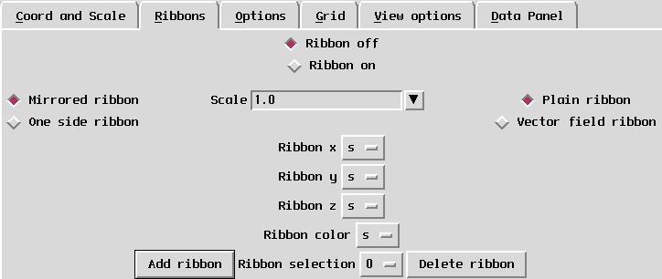
This page, shown in Figure, can be used to add one or several ribbons to the solution.
The Ribbons page for the
General AUTO Data Probe module.
All the ribbons can be turned on and off by using the "Ribbon on/off" buttons on the top center of this page. In the beginning, these buttons will only activate one ribbon. If several ribbons are defined afterwards, they will turn on and off all the ribbons attached to the solution.
The line below the "Ribbon on/off" buttons contains general properties that apply to all the ribbons at once.
The first one, linked to the left buttons on this line, allows the user to choose between a mirrored ribbon (symmetrical towards the centerline of the solution) and a one-sided ribbon. The default option is mirrored.
The second one, linked to the typein labeled "Scale" on the center on the line, scales all the ribbons with a real value.
The last one, linked to the top right buttons on this line, allows the user to choose between a ribbon drawn as a surface (plain) and as a vector field. By default the ribbons are drawn as surfaces.
The four menus at the center of the page define each of the ribbons attached to the solution. The first three menus set the columns of the data used for the x, y, and z coordinates of the ribbon. The values in these columns are used relatively to the centerline. Thus, in each point of the solution, the ribbon will be defined by a vector with the origin on the centerline and with offset defined by the 3 coordinates.
A fourth coordinate sets the color the ribbon in relation with a column of the data. The ribbon also uses the colormap defined on the View Options page (see below).
These four coordinates are specific to each ribbon, and their values concern the current ribbon (see Ribbon selection below). By default they all have the 0 value, which usually designs the variable "s".
The bottom line on this page allow the user to work with several ribbons attached to the same solution. The first button on this line, labeled "Add ribbon", adds a new ribbon to the solution, as its name states its. The particularity of this operation is that if the ribbons are off, they will be turned on, without adding a new ribbon. A consequent message will also be printed on the standard output.
The next widget on this line, labeled "Ribbon selection", allow to choose the current ribbon. This selection will have the effect of setting all the values on the middle line as being the ones of the selected ribbon. It also designates the ribbon number to be deleted by the "Delete ribbon" operation. When adding a new ribbon, this value will automatically be updated to the last ribbon number, so the new ribbon can be set right away.
The next button, labeled "Delete ribbon", will delete the current ribbon. If the ribbon is the last added, then the current ribbon becomes the previous one. Otherwise, the current ribbon conserves its number, but of course, its identity is different, because the remaining ribbons are shifted. The coordinates of the ribbon are also updated according to the current ribbon selection. The particularity of this button is that if there is only one ribbon left, it will not be deleted, but turned off instead. A consequent message is also printed on the standard output.
Note. Any of the described actions on this page will not have any visual effect until the "Draw" button is pressed.
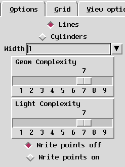
This page, shown in Figure, controls the setting of general visualization options. At the top of this page are two toggle buttons. If the top button (marker "Lines") is selected then the solution will be rendered as lines (i.e. unshaded). If the bottom button (marker "Cylinders") is selected then the solution will be rendered as tubes (i.e. shaded). The next widget is marked "Width" and is used to set the width with which the solution is drawn.
The Options page for the
General AUTO Data Probe module.
WARNING: The width has different interpretations depending on whether "Lines" or "Cylinders" is chosen. For "Lines" it is number of pixels, and for "Cylinders" it is the radius of the cylinder. The graphics may look quite strange if the drawing method is changed without making the appropriate change to the width. For example a value of "3" may be perfectly reasonable for the number of pixels in a line, but far too large for the width of the cylinder.
The next two controls on this page are two sliders with which the user can control the lighting complexity and the geometry complexity. The exact definition of these values is beyond the scope of this manual, but the idea is that these allow the user to trade image quality for rendering speed. Low values of these sliders make the image render faster, but are lowering image quality (e.g. smaller number of triangles per sphere, turning off shading), while high values render more slowly but are of higher quality. "7" is the default value and the user is encouraged to experiment to find values which are good balance between speed and quality.
Finally, there are two toggle buttons "Write points off" and "Write points on" which control the production of additional debugging output. If the "Write points on" button is selected, then the centerline of the solution will be printed on the standard input. This feature can be useful to see the actual values in the solution. For general usage the "Write points off" should be selected.
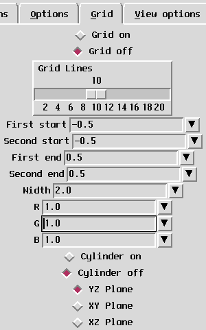
The "Grid" page, shown in Figure, controls the appearance of the grid in the Data Probe window.
The Grid page for the
General AUTO Data Probe module.
The toggle buttons "Grid on" and "Grid off" control whether the grid appears or not. The slider labeled "Grid lines" allows the user to set the number of lines to be used in the creation of the grid. Higher numbers make the grid "denser". The "First Start", "Second Start", "First End", and "Second End" type-ins allow the use to define the coordinates of two opposite corners of the grid so that it may be moved around. The "R","G", and "B" type-ins control the color of the grid, while the "Cylinder on" and "Cylinder off" toggles whether the grid is drawn as lines (i.e. no shading) or as cylinders (i.e. shading). The "Width" type-in in interpreted as number of pixels when the grid is drawn without shading and as the radius of the cylinder when it is drawn with shading. Finally, the three toggle buttons labeled "YZ Plane", "XY Plane", and "XZ Plane" control the orientation of the grid.
The "View options" page, shown in Figure , allows you to set the axes options, to choose the colormap and to perform some file operations.
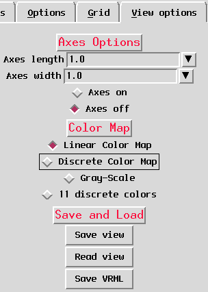
The View Opions page for the
General AUTO Data Probe module.
The "Axes Option" section of this page controls the appearance of the coordinate axes in the bifurcation diagram window. The "Axes length" type-in controls the length of the axes, while the "Axes width" type-in allows the user to enter the width of the axes in pixels. Finally, the "Axes on" and "Axes off" toggle switch may be used to control whether the axes appear in the window or not.
Note, the axes always appear at the center of the coordinate system for the bifurcation diagram (after any translations have been applied). Accordingly, the bifurcation diagram always spins around the origin of the axes.
DataViewer provides several different color maps which may be used to translate floating point values into colors (i.e. RGB values). In DataViewer a color map is a function defined over some range of floating point numbers (defined by a minimum and maximum value) which returns an RGB triple. An example of such a function might assign black to the minimum value, white to the maximum value, and interpolate values in between as some shade of grey. Another example might assign blue to the minimum value, red to the maximum value, and the interpolate values in between to create a "rainbow" (we note that while the idea of a "rainbow" which smoothly varies from blue to red may be quite intuitive, the actual implementation of such a colormap can be somewhat subtle).
Normally VBM will compute the minimum and maximum values for the color map by using the appropriate column of data over the entire bifurcation diagram.
The "Colormap" section of the "View options" page allows the user to choose from three different colormaps for the visualization of their data. The "Linear Color Map" sets the minimum value to blue, the maximum value to red, and uses a "rainbow" in between. The "Gray-Scale" color map sets the minimum value to black, the maximum value to which, and uses shades of grey in between. The "Discrete Color Map" color map is different from the previous two in that it only returns colors at integer values and white everywhere else. It is a special purpose color map and it probably not useful for general visualization problems.
One color map which is somewhat specialized is the "11 discrete colors" colormap. In this colormap points of the bifurcation diagram are divided into eleven groups, and two points are placed in the same group if the values in their columns defined by "COLOR Coordinate" are sufficiently close. The eleven colors in this colormap have been chosen to have the highest color separation possible (i.e. they are easy to tell apart from each other). If there are more than eleven groups of values then the twelfth and higher groups are all assigned the color white.
The "Save and Load" section of this page contains buttons for saving and reading information about the bifurcation diagram, including saving it in other formats.
Save View
There are many parameters which make up how a specific bifurcation diagram appears, e.g. its current rotation, width, what columns have been selected, etc. The file chooser activated by this button may be used to save a file which contains all of the parameter for the current visualization so that it may be read in later to recover the same view.
Read View
The file chooser activated by this button may be used to read in a view file which was previously saved with the "Save View" operation. Note, the contents of the view file depends on the VBM file which was being visualized at the time the view file was created. If you attempt to read in a view file which was created for a different VBM file then you are currently visualizing the behavior is undefined (it may work, but will probably not do what you expect!).
Save VRML
This button will soon be used to save a VRML version of the current bifurcation diagram. This functionality is under construction and this module does not use it yet.
This page contains two buttons, used respectively to iconify and deiconify the data panel.